Posted on

Airide Firestone air spring components

1. Studair-spring-components

A permanent part of the bead plate assembly used to attach the airspring to the suspension.
2. Combo Stud
Combination mounting stud and air fitting.
3. Blind Nut
A permanent part of the bead plate assembly providing an alternate mounting system to the stud.
4. Air Fitting Hole

A tapped hole usually 1/4″ N.P.T. providing air entrance for the part.
5. Bead Plate

Permanently crimped onto the bellows at the factory allowing complete part leak testing prior to shipment.
6. Bellows
The heart of an Airide spring. Includes at least four plies, or layers, of material–an inner layer, two plies of cord-reinforced fabric, and an outer layer.
7. Bumper (Optional)

A solid molded rubber fail-safe device used on many suspension applications. Prevents excessive damage to vehicle and suspension in the case of sudden air pressure loss.
8. Piston
The lower section of the 1T and 1X style of airspring made from aluminum, steel or fiber reinforced plastic. Provides lower mounting arrangement for the airspring in the form of tapped holes or studs.
9. Piston Bolt

Attaches the piston to the bellows assembly. Extended, in some cases, to serve as a means of attaching the spring to the suspension.
10. Girdle Hoop

A ring between the convolutions of the convolutedtype air spring.
Service Assembly
On Firestone Airide springs of the 1T style, the rubber bellows bead plate portion of the spring is a separate hermetically sealed unit, available for replacement use without the piston. Called a “service assembly,” it includes a bead plate, bellows, internal bumper (if any), and all attaching hardware.

Now that you know the parts and components of an air spring, here are some tips on how to identify an air spring

Posted on

Air Compressor Troubleshooting

Air Compressor Troubleshooting

Compressors that are passing excessive oil as evidenced by the presence of oil at valve exhaust ports or seeping from air inlets is usually a result of:

  1. Restricted air intake – Check the compressor air filter and replace as necessary. Check the compressor air intake hose for kinks, excessive bends, and a minimum ID of 5/8″.
  2. Restricted oil return – Do not use sealers on mounting gaskets as this could result in diminished oil return on some compressors. Check the bottom oil drain line on compressors that use this feature to ensure that there are no bends where oil could pool and that the minimum ID is 1/2″.

Causes of slow air pressure build times are:

  1. Dirty intake filter or restricted intake line
  2. Restricted discharge line or compressor discharge cavity
  3. improperly functioning unloaders or governor

Common causes of high head pressure and resulting failure are:

  1. Discharge line is kinked or clogged with carbon
  2. Water traps in discharge line causing line freeze-up
  3. Discharge line smaller than the minimum recommended 1/2″ ID
Posted on

D-2 Air Governor

D-2 Air Governor

Never condemn or adjust the governor pressure settings unless you have checked pressure with an accurate test gauge or a dash gauge that is registering accurately. Standard dash gauges are only required to be accurate to within +/- 10 percent.

d-2-style-air-compressor-governor

Remember the following if adjustment is necessary:

  1. Turn the adjusting screw counter-clockwise to lower the air pressure setting.
  2. Turn the addjusting screw clockwise to increase the air pressure setting.
  3. Be careful not to overadjust. Each quarter turn of the adjusting screw raises or lowers the pressure setting approximately 4 psi.
  4. The cut-in and cut-out range is not adjustable.

The most common cause of governor failure is contamination. Blow out all attaching lines, hoses, etc when replacing a governor. Make sure the reservoir pressure sensing line is routed from the reservoir so that no contamination may enter the line and pass into the governor. A replacement D-2 air governor can be found here.

Posted on

General Air System Valve Troubleshooting

Valve leakage is commonly caused by, but not restricted to:

  1. Contamination caused wear, damage, or sticking of the valve’s operating parts
  2. Application of air pressure to a valve’s delivery port from another device in the air system

Determine the port(s) improperly emitting air pressure and perform the following service checks:

  1. Exhaust port leakage at rest – Disconnect the delivery lines. If the leak stops, inspect the device at the other end of the delivery line for leakage. If the leakage continues, inspect and repair or replace the leaking valve.
  2. Delivery port leakage at rest – Consult the appropriate service manual for specific test procedures.
  3. Exhaust port leakage during application – Consult the appropriate service manual for valve specific test procedures.

Always blow out all attaching lines and reservoirs when installing a replacement valve to purge any contamination from the system. Avoid using thread sealant or tape as excess material can itself contaminate the air device.

Posted on

Air Valve Part Number References

There is no application guide that tells us what air brake valves the manufacturer used on your truck or trailer. The only people who can tell you what valve the vehicle manufacturer used based on a VIN are the vehicle dealers. With that said, there are other ways to determine which valve you need. You may find a label or a metal tag on the valve that has the OEM part number printed on it. Sometimes, the number is stamped right on the valve body. Raised casting numbers are usually no help at all. You’re looking for stamped numbers here.

If you can’t find any numbers, you can look for a match based on the pictures we provide here on AnythingTruck.com. This is easiest if you know at least what type of valve you’re working with. Is it a relay valve or push-pull valve? If you have no idea what kind of brake valve you’re replacing, you will probably benefit from looking over the Bendix Air Brake Handbook.

We try to provide a comprehensive cross reference lists for each air brake valve we offer here, but there are always OE numbers we haven’t learned about yet. The list of pages below contains useful part number references from OE valve manufacturers. You can try your part number at the sites listed or just give us a call or drop us an email for help.

  • Bendix Part Number Search Use this if you have a Bendix part number and want to find their current number.
  • Bendix Cross Reference Cross reference a vehicle manufacturer’s part number to a Bendix number.
  • Haldex Cross Reference If Haldex made it, they should be able to cross reference for your number to the current number. Look at the right side of the page for the cross reference search box.
  • Meritor Parts Online Use the search box at the top of the page.
Posted on

How Spring Brakes Function ?

The spring brake assembly is bolted to a mounting bracket on the axle. The spring brake pushrod clevis is attached to a slack adjuster which is attached to a camshaft. As the spring brake pushrod is extended from the chamber, either by the parking/emergency brake or by service air pressure, the linear force of the pushrod is converted to rotational force by the slack adjuster and camshaft. This spreads the brake shoes against the brake drum.

When air is applied to the parking/emergency brake, the load of the heavy spring is released allowing the wheels to turn. When the driver steps on the brake pedal, a signal is sent to a relay valve that then sends air pressure to the service chamber of the spring brake. The air pressure causes the pushrod to extend which in turn applies the brake. This air pressure is released once the driver takes his or her foot off of the brake pedal.

The spring brake is designed to apply the the brakes automatically in the event that there is a loss of system air pressure. This happens because the air pressure holding back the heavy parking/emergency spring disipates allowing the spring to extend the pushrod which in turn applies the brake.

Posted on

What is difference between Spring Brake Actuator and Brake Chamber?

Brake chamber and spring brake actuators are used in Air braking system. mostly in heavy vehicles (Trucks).

Brake chambers are used in Front axles and spring brake actuators in Rear axles.

The main difference between Spring brake actuator and brake chamber is, Brake chamber doesn’t have hand-brake function but Spring brake actuator does have hand-brake function.

Brake chamber:
Brake-chamber
It has only one function, whenever air enters into the chamber, diaphragm  gets expand and pushes the pushrod then the push rod pushes the slack adjuster then slack adjuster rotates the S-cam shaft and so on. when driver releases the brake pedal the return spring push back the diaphragm to its original position

Spring brake actuator:

 Brake-chamber-1

See that GIF pic (donno GIF works on all devices), The red color one is second chamber , and blue one is normal brake first chamber. there is separation between those two chambers and there are different diaphragms for each chamber. (Refer the image)

First chamber/service brake chamber (Blue color) : when driver applies the brake , pressurised air enters into first chamber(See that blue colour), diaphragm expands and the diaphragm  pushes the pushrod hence brakes applied. (Just like brake chamber working)

second chamber/Spring brake chamber (Red color): in this chamber pressurised air is available all the time, this pressurized air holding back the Large coil springs  not to expand which connected to pushrod . so whenever driver applies the HandBrake the pressurized air which was holding the springs in second chamber gets released into atmosphere hence the large coil springs get expanded and pushes the Pushrod.

Posted on

Ordering a Meritor WABCO System Saver Twin air dryer

Meritor WABCO System Saver Twin Air Dryers

System Saver Twin air dryers are designed for trucks with high air use requirements. One cartridge is drying air while the other is regenerating. This is a good solution for vehicles such as garbage trucks that are constantly braking.

650-sstwin

Ordering a Meritor WABCO System Saver Twin air dryer

We sell all System Saver Twin dryers as non-returnable special orders. We’ll need a part number from your existing air dryer. You can find it on the metal ID tag, and it will look like 432 431 016 0. For new installations, you will need to determine the compressor’s rating in CFM and whether you need a 12-volt or 24-volt heater/thermostat.

System Saver Twin Repair Parts

Most repair parts can be special ordered for the System Saver Twin. Download the parts list/troubleshooting document from the link above. Call or email when you’ve determined which parts you need, and we will get you the current price and availability of those items.

Other size:

Posted on

How Bendix AD-9 Air Dryers Work

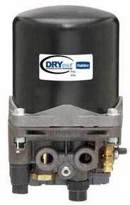
Bendix AD-9 Air Drying Process

The information on this page describes how the Bendix AD-9 functions during normal operation. You should see our AD-9 troubleshooting information or download the Bendix AD-9 Service Data Sheet if you’re trying to diagnose a problem with your air dryer. We also sell new AD-9s as well as AD-9 service parts.

060-065225_200

OVERVIEW

Every truck with air brakes has an air compressor on the engine. The air compressor keeps the air tanks full, so there is always air available to stop the truck. All air has a certain level of humidity which means that there is always water vapor in the atmosphere no matter if you’re in a dry or damp climate. Air is heated as it’s compressed, and it cools as it travels through the discharge line to the air tank. This cooling results in condensation creating pools of water in the bottom of the truck’s air tanks. You will also find oil from the compressor and any contaminants that made it through the compressors air filter in the the water.

Air dryers were created to minimize the amount of moisture and other contaminants that make it to the air tanks. The Bendix AD-9 air dryer alternates between two modes or “cycles” during use, the charge cycle and the purge cycle. Both cycles play an important part in keeping your air tanks as clean as possible.

AD-9 CHARGE CYCLE

With an AD-9 air dryer installed, contaminants enter the supply port of the air dryer end cover. As the compressed air travels through the end cover assembly, its direction of flow changes several times causing contaminants to condense and drop to the bottom of the air dryer end cover.

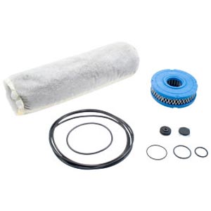
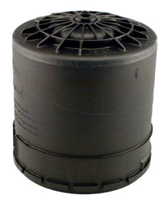
The compressed air exits the end cover and flows into the desiccant cartridge where it flows through an oil separator that removes any water as well as oil and solid contaminants. The air then leaves the oil separator and enters the desiccant drying column. The moist air flowing through the column of desiccant becomes progressively drier as the water vapor absorbs into the desiccant material. The desiccant cartridge removes 95% of the water vapor from the pressurized air.

Most of the dry air exits the desiccant cartridge through a built-in single check valve and fills the purge volume 060-AD9-Cross-Section

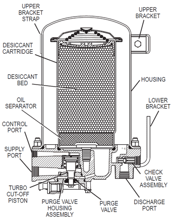
between the desiccant cartridge and outer shell. Some air exits the desiccant cartridge through the purge orifice near the check valve.

The dry air is then moved out of the purge volume through the single check valve and out the delivery port to the first (supply) reservoir of the air system. The air dryer stays in the charge cycle until the air brake system pressure reaches the governor cutout setting.


AD-9 PURGE CYCLE

The purge cycle of the air dryer begins when the governor causes the compressor to unload (stop compressing air). During compressor unload, the line connecting the governor unloader port to the AD-9 air dryer end cover control port is pressurized. The air pressure causes the air dryer purge valve to open. Contaminants in the end cover sump are expelled immediately when the purge valve opens. At the same time, the air that was traveling through the desiccant cartridge reverses direction and begins to flow to the open purge valve removing oil and solid contaminants collected by the oil separator.

The initial purge and desiccant cartridge decompression happens in just a few seconds and is evidenced by a burst of air at the AD-9 air dryer exhaust.

The flow of dry air through the desiccant cartridge drying bed reactivates the desiccant material by removing the water vapor it previously absorbed. It normally takes 15-30 seconds for the entire purge volume to flow through the desiccant drying bed.

The single check valve in the AD-9 end cover keeps air pressure in the brake system from blowing back into the air dryer during the purge cycle.

The purge valve will not close until air brake system pressure is reduced and the governor signals the compressor to begin compressing air again. That will start the next charge cycle.
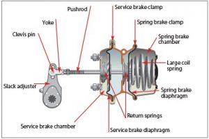
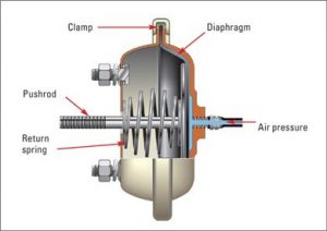
Posted on

Ordering a SKF Turbo-2000 air dryer and SKF Service Parts / Repair Kits

The Turbo-2000 is an excellent choice for severe service, stop-and-go operation. It features a large purge volume to desiccant ratio that results in ideal filtering and contamination prevention. Turbo-2000 can be used with compressors up to 30 CFM with duty cycles as high as 40%.

170-Turbo2000_a

Ordering a SKF Turbo-2000 air dryer

We sell all SKF dryers as non-returnable special orders. Call or email us with your requirements, and we will get you the current price and availability.

Turbo-2000 Service Parts / Repair Kits

Posted on

Ordering a Haldex Pure Air Plus air dryer

Pure Air Plus are usually found on coach chassis from the 1990s. Haldex is no longer producing new Pure Air Plus dryers, but remanufactured units are still available.

Ordering a Pure Air Plus air dryer

We sell all Pure Air Plus dryers as non-returnable special orders. We’ll need a part number from your existing air dryer or the vehicle manufacturer’s part number in order to determine the current Haldex aftermarket part number. The part number on your existing air dryer will usually start with a ‘N’ followed by numbers and maybe another letter, such as N4250 or N4250C.

1.Haldex DA33100X 12-Volt Pure Air Plus Air Dryer, No Bracke

070-DA33100

  1. Manufacturer: Haldex
  2. Part Number: DA33100X
  3. Condition: Remanufactured, Core charge required
  4. Pure Air Plus air dryer
  5. For use in standard air -brake applications on truck, tractors, and buses
  6. 12 volt DC heater
  7. Supply Port: 1/2″ NPT
  8. Delivery Port: 1/2″ NPT

Core Charges
This item carries a core charge that is fully refundable with the return of your rebuildable Haldex core. It MUST be a Haldex brand Pure Air Plus core. You will need to ship your core freight prepaid to the address on your receipt. Include a copy of your receipt, so we can apply your core refund to the proper order.

Cross References: DA33100, N4250, N4250C, N4250C, N4250D, N4250E, N4250F, N4250H, N4250K, N4250N, N4250P, N4250R, N4250R, ZZDA33100, 201644C91, 2016744C91, 2016744C92, 767653009377
A cross reference listing means that this air dryer is a suitable replacement for the part numbers listed. Some changes in plumbing and/or installation may be required.

  1. This air dryer is NOT compatible with Cummins Holset compressors
  2. Does NOT include new mounting bracket

Haldex Pure Air Plus Repair Kits

A.Haldex DQ6011 12-Volt Heater Kit for Pure Air Plus Air Dryers, Dryers Dated Prior To 09/1997

070-DQ6011

Manufacturer: Haldex

Part Number: DQ601112-

Voltheater kit for Pure Air Plus air dryers

For dryers date coded prior to 9/97

Fits the following Pure Air Plus models: DA33100, DA33100X, DA33100BX, DA33140, DA33140X, DA33200, DA33200X, DA33240, DA33240X

 b.Haldex DQ6020 Lower Housing Repair Kit for Pure Air Plus Air Dryers
070-DQ6020
Manufacturer: Haldex
Part Number: DQ6020
Lower housing repair kit for
Pure Air Plus air dryersIncludes purge valve, turbo saver, and one-way check valve assemlies
Fits the following
Pure Air Plus models: DA33100, DA33100X, DA33100BX, DA33110, DA33110X, DA33140, DA33140X, DA33200, DA33200X, DA33240, DA33240X, DA33105

C:Haldex DQ6026 General Service Kit for Pure Air Plus Air Dryers, Includes Desiccant Cartridge

070-DQ6026

Manufacturer: Haldex
Part Number: DQ6026
General service kit for Pure Air Plus air dryers
Includes desiccant cartridge, coalescing filter, relief valve, purge shield, and associated hardware
Fits the following Pure Air Plus models: DA33100, DA33100X, DA33100BX, DA33110, DA33110X, DA33140, DA33140X, DA33200, DA33200X, DA33240, DA33240X, DA33105

Cross References: DQ6022, DQ6036, DA33120, 201160C
A cross reference listing means that this part should be a suitable replacement for the part numbers listed.

Other size:


Posted on

Ordering a Haldex “Pure Air” air dryer

Pure Air air dryers are an older dryer model that is still found on the road today. They can be mounted horizontally or vertically, and they are serviceable from either end.

Ordering a Pure Air air dryer

We sell all Pure Air dryers as non-returnable special orders. We’ll need a part number from your existing air dryer or the vehicle manufacturer’s part number in order to determine the current Haldex aftermarket part number. The part number on your existing air dryer will usually start with a ‘N’ followed by numbers and maybe another letter, such as N4244 or N4244A.

Haldex Product:
1.Haldex KN33000 12-Volt ‘Pure Air’ Air Dryer, Standard Size, OEM# N4244
2.Haldex KN33010 24-Volt ‘Pure Air’ Air Dryer, Standard Size, OEM# N4244A

070-KN33000

Product Description
Manufacturer: Haldex
Part Number: KN33000,KN33010
OEM Number: N4244,N4244A
Condition: New
“Pure Air” air dryer
New air dryer, no core charge
For use in standard air -brake applications on truck, tractors, and buses
12 volt DC heater/24 volt DC heater
Supply Port: 1/2″ NPT
Delivery Port: 1/2″ NPT
Cross References: ZZKN33000X, F4HS2A131BA, N4244
A cross reference listing means that this air dryer is a suitable replacement for the part numbers listed. Some changes in plumbing and/or installation may be required.
Special Notes:This air dryer is NOT compatible with Cummins Holset compressors

2.Haldex Pure Air air dryer kit:
Midland Haldex Pure Air Air Dryer Major Maintenance Kit

070-RN60A

Manufacturer: Haldex
Part Number: RN60A
Major service kit for Midland/Haldex Pure Air air dryers
Includes desiccant bag, filter, o-rings, check valve seal, and purge valve seal
Cross References: RN60A, 5396-RN60A, 1645921C91, 86130027, 767653020242, MIDRN60A

Other size:

Posted on

Ordering a Haldex DRYest air dryer and Kit

DRYest air dryers integrate the turbo protection valve, governor, regeneration valve, muffler, and heater into one compact package to ensure extended system life with lower initial costs. It fits in an area as small as 12″ x 6-3/4″ x 6-3/4″.

  1. Haldex 47178964 DRYest Air Dryer Desiccant Cartridge Kit

    070-47178964070-Dryest

  2. Manufacturer: HaldexPart
    Number: 47178964
    Condition: New
    Desiccant cartridge kit for Midland Haldex DRYest air dryers
    mounting bolts, o-ring, bolt anti-seize, and installation instructions
    Fits the following DRYest models: DA35100, DA35105, DA35110, DA35115, DA35200, DA35205, DA35210, DA35215, DA35220
Ordering a DRYest air dryer

We sell all DRYest air dryers as non-returnable special orders. We’ll need a part number from your existing air dryer or the vehicle manufacturer’s part number in order to determine the current Haldex aftermarket part number. The part number on your existing air dryer will usually start with a ‘N’ followed by numbers and maybe another letter, such as N4260 or N4260A. Please call or email us with that information in order to get the latest pricing and availability.

Other size: